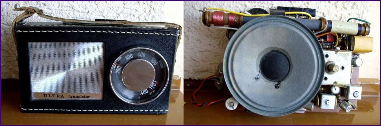
For folowing reflections I used the Ultra radio.
This radio has 3 HF transistors AF117, 3 intermediate frequency stages.
All of these AF117 were totally unstable in a strange mode. Sensitive by touching their surface, changing their behaviour from moment to moment. Unbelievable, incredible, I had to exchange one after other by another suitbale Ge-transistors (GF506).
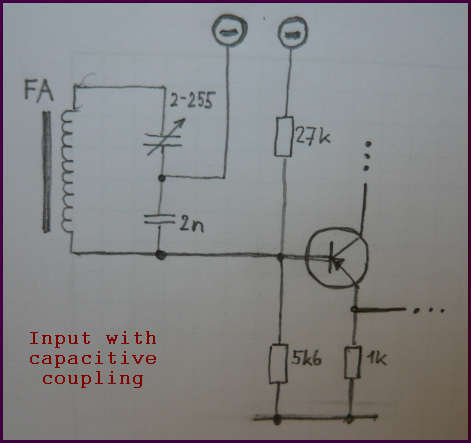
First transistor works as oscillator, mixer-converter and as input and first IF amplifier.1. picture:Input ferrite antenna circuit is coupled to the basis of first transistor thru a capacitive divider:
Disadvantage of such solution is changing of the divider ratio with changing the tuning capacity.
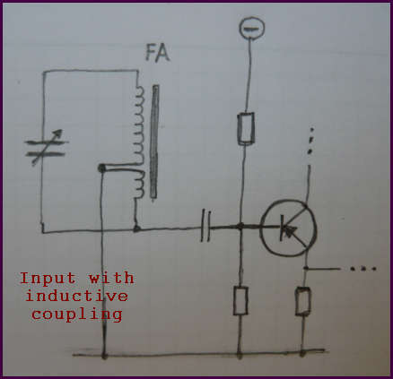
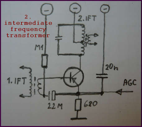
2. picture:In most radios an inductive coupling instead of capacitive is used.
The divider serves for impedance transformation in order to match the first transistor input impedance. A direct coupling would damp too much the resonance circuit.
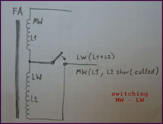
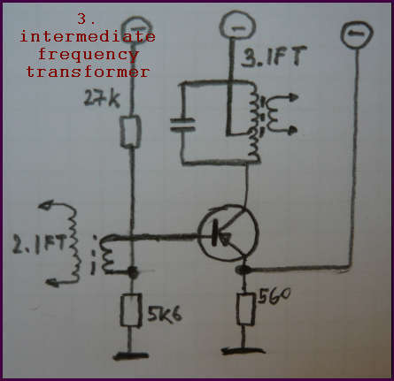
3. picture shows one possibility to switch inductivity coils between MW/LW. For MW the second winding is short cutted, for LW both windings work in serial connection. Another often used possibility is an extra winding for Mw and LW.
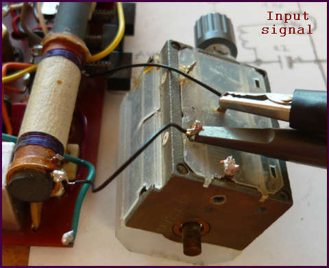
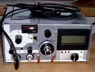
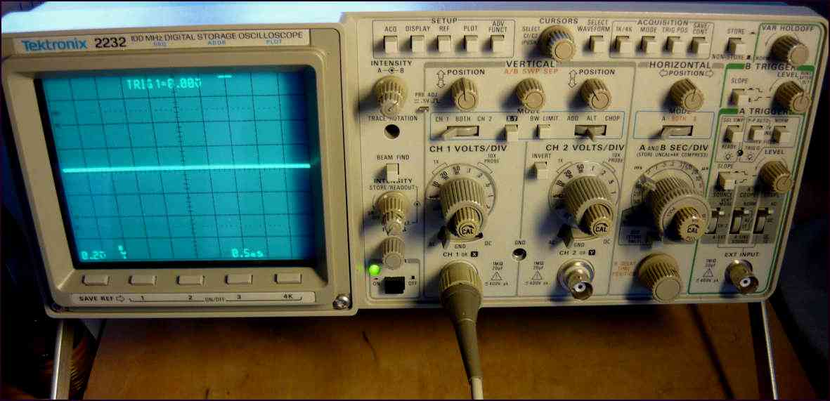
Oscilloscope with a probe 10 Mohm/12pF directly coupled on the input resonance circuit shows about 1 to 10 mV peak-peak:
On the collector of 2.IF there was about 10 to 100 mV, on the collector of 3.IF about 200mV-2V.
We have to take in account, that the 1.IF stage has to transform down the high impedance of the input circuit, therefore the main reason is the current amplification, which means impedance transformation.
The first transistor works also as a mixer at a working point, which is not optimal from amplification point of view.