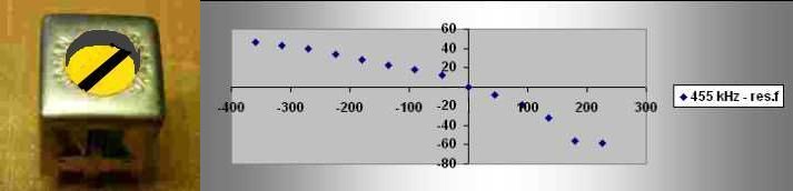
Measuring on intermediate frequency transformer (IF) for Medium wave (MW).
Dependency of the resonance frequency on the position of transformer core.
Yellow transformer
Turn left (up)
IF
Turn right (down)
Core turn [deg]
-360
-315
-270
-225
-180
-135
-90
-45
0
+45
+90
+135
+180
+225
Resonance frequency [kHz]
501
498
494
489
483
477
473
467
455
447
437
423
399
397
inductivity [µH] with C=200pF
500
600
800
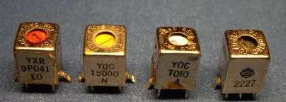
Left picture is a typical stuff of cans in an MW radio: red-oscillator, yellow-1.IF, white-2.IF, black-3.IF.
The IF transformers have their capacitors on the bottom part of the can - visible on the right picture.
From table values we see, that the core position has to be adjusted accurately.
Otherwise the strength of output signal and selectivity will be reduced.
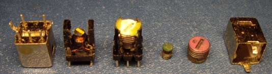
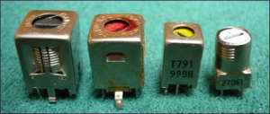
Different shapes used for IF transformers:
The parallel capacitance can be placed in a cave at the bottom of the transformer, but not always.
The value at AM radio for 455 kHz is often 200pF, but also 500pF, 1000pF and even more.
At FM radio for 10.7 MHz by L=4.4 µH is it 50 pF, also lower values are used in combination with larger inductances.
Reminder: fres = 1 / (2*π*√L * √C)
The reciprocal racio of fres from L and C is weakened due to the square roots over L and C.
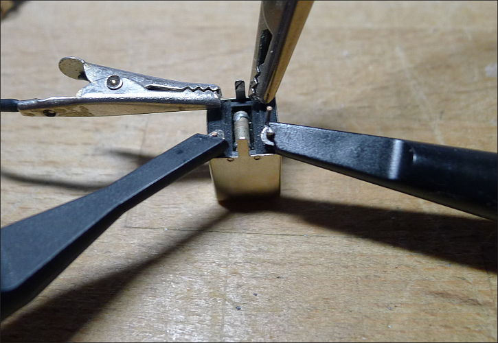
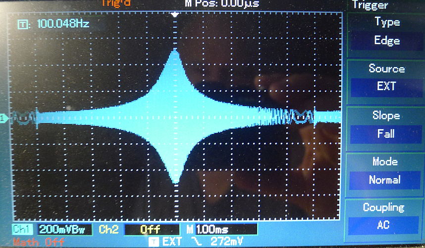
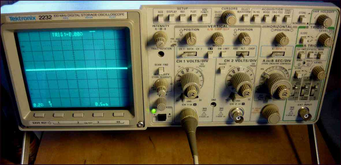
Resonance frequency of a yellow MW IF transformer.
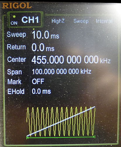
I used a sinus generator with sweep facility and a standard scope with external triggering possibility.
The probe capacity with a probe set to 10:1 is about 10pF, which causes shift of the resonance frequency, because it is parallel to the 180 pF built-in capacitor with a 680µH inductivity coil.
It shifts the 455kHz down to 443kHz.