| Round FA #1 | Dependency of the inductivity from the placement of the winding from one border to center (23 mm). | |||||||||||
|---|---|---|---|---|---|---|---|---|---|---|---|---|
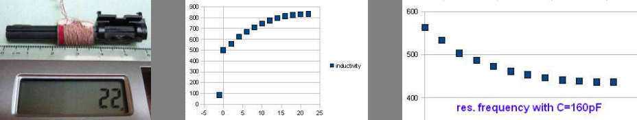
| distance from the border of the ferrite rod [mm] | 0 | 2 | 4 | 6 | 8 | 10 | 12 | 14 | 16 | 18 | 20 | 22 |
| measured inductivity L(µH) | 500 | 558 | 624 | 668 | 708 | 746 | 773 | 795 | 813 | 824 | 832 | 834 |
| difference between two adjacent values ΔL(µH) | 58 | 66 | 44 | 40 | 38 | 27 | 22 | 18 | 11 | 8 | 2 | |
| calculated res. freq. with C=20pF [kHz] | 1590 | 1510 | 1420 | 1380 | 1340 | 1300 | 1280 | 1260 | 1250 | 1240 | 1230 | 1230 |
| calculated res. freq. with C=160pF [kHz] | 563 | 533 | 503 | 487 | 473 | 461 | 453 | 446 | 441 | 438 | 436 | 436 |
This experiment measures the dependency of the inductivity on the position of the winding on the ferritte rod of antena FA #1 and makes some comparisons to FA #2. For tuning an MW receiver is usefull to know, how sensible is the position of the winding on FA.
On the lower frequency border of MW (531 kHz) we have to shift the winding on ferrite in order to adjust the input circuit with oscillator circuit so, that the resonance frequencies difference of both will be the intermediate frequency (IF) of the radio receiver.
We do it obviously in some distance of the low frequency border to achieve best collaterality in the whole frequency range. (At the higher frequency border we use tunig capacitors - again at some lower frequency - 2 tuning points.)
The IF could be 455, but also 460, 465 or 468 kHz, other IF's are also possible. Therefore on the selected frequency we use to shift the winding into the best position to gain the maximum signal on the diode output under assumption, that intermediate frequency filters are correctly adjusted.
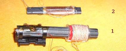
Inductance of FA#2: (L=425 µH - winding placed as on the picture,
- winding at the border-distance 0 mm:L=320 µH)
Inductance of FA#1 is higher as the inductance of FA#2.
Inductance of the winding without ferrite FA#1(round): 86 µH, FA#2(flat): 18 µH.
Inductance of 10 windings on FA#1(round): 7 µH, on FA#2(flat): 5 µH.
Own resonance frequency with ferrite (without any external capacitor)
FA#1(round): 1.53 MHz, FA#2(flat): 1.94 MHz; (winding placed as on the picture).
Note: On the higher frequency border we adjust with capacity trimmer, which is often placed directly on the variable capacitor.
Worked with: