Accu load and measurement
Loading devices
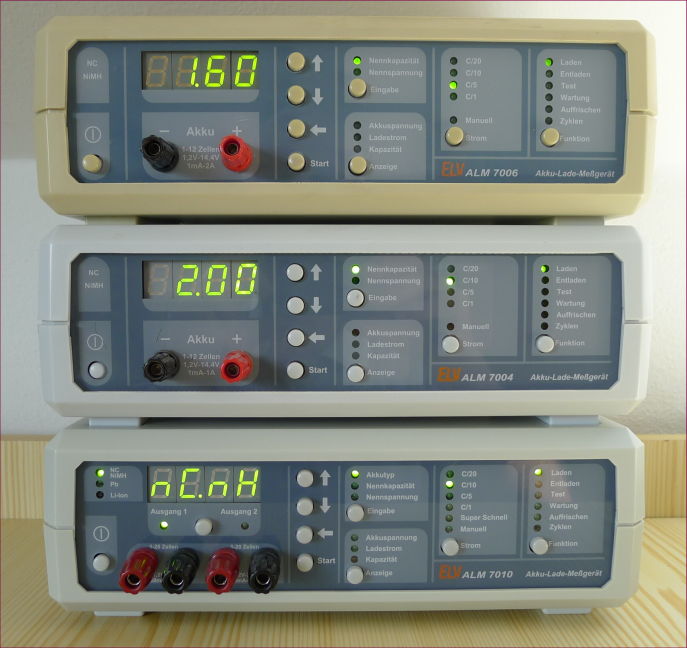
ELV has produced ALM devices for testing and loading accumulators with unique design and similar wiring.
The predecessors of all the devices below were ALM7000 and ALM7001 with identical front panels.
| ALM7000: |  |
| ALM7001: |  |
| device | max U | max I | digits | outputs | accu types | serial conn. | +feature |
|---|---|---|---|---|---|---|---|
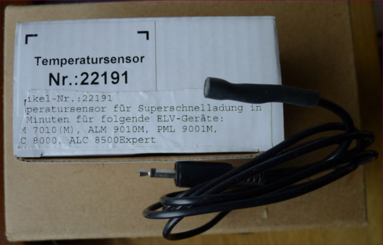
| ALM 7002 | 30 V | 3.5 A | 4 | 2 | NiCd, NiMH, Pb, Li-ion | no | ext.temp.sensor |
| ALM 7003 | 18 V | 1 A | 3 | 1 | NiCd, NiMH | no | . |
| ALM 7004 | 18 V | 1 A | 4 | 1 | NiCd, NiMH | Y | . |
| ALM 7005 | 18 V | 2 A | 3 | 1 | NiCd, NiMH | no | fan |
| ALM 7006 | 18 V | 2 A | 4 | 1 | NiCd, NiMH | Y | fan |
| ALM 7010 | 30 V | 3.5 A | 4 | 2 | NiCd, NiMH, Pb, Li-ion | Y | ext.temp.sensor |


ELV ALM 7006 - NiCd and NiMH loading (charging) and measuring device.
PC control and data logging software for controlling, drawing, and storing graphical values using RS232 connectivity.
Working with 80C32 processor and 14 bit analog to digital dual slope converter.
Maximal charging voltage 18V (12 elements), loading current 10 mA - 2A settable,
automatically finishing of charge and discharge phase.
Unload power transistor: BD249 NPN max.125W and 25A. Load power transistor BD244 PNP max 65W and 6A.


ELV ALM 7006 - fan and temperature control.
After replacement of the power transistor BD249, which was destroyed together with his emitor resistance 0.18Ω after reversed connecting the poles of an accumulator I have also put a new white paste to both temperature sensors SAA965.
The first sensor on the trafo is only pressed to the trafo plates, the second one on the cooler is better adjusted.
After these changes during loading of an accumulator after approx. one hour the fan started to run.
At this moment the temperature of the trafo plates was 50°C, the temperature of the cooler was only 35°C.
Measured values:
The voltage at the sensor: 1.58 V, at begin: 1.4 V.
| 0°C | 20°C | 25°C | 40°C | 50°C | 60°C | 80°C | 100°C |
| 810Ω | 960 Ω | 1000Ω | 1120Ω | 1210Ω | 1300Ω | 1500Ω | 1700Ω |
The resistance-temperature characteristic of the sensor SAA965 (working as PTC resistor) is nearly linear.
There is a potential divider between 5 V, a 2.55kΩ resistor, SAA965 value and 0 V (see diagram).
Calculated values:
At the start the sensor temperature was 25°C ==> 1000Ω. Calculated divider voltage: 5V * 1000 / 3550 = 1.4 V is the same as value measured.
At the end the sensor temperature was 50°C,==> 1210Ω. Calculated divider voltage: 5V * 1210 / 3760 = 1.6 V, what is nearly the same as measured.
The potential is multiplexed to the processor and he gives the command to run or stop the fan.
The fan is noisy, therefore I have released a bit the contact of the sensor with the trafo plates.
But my suspicion is, that there went something wrong with the trafo and therefore it produces more heat as before the destruction of BD249.
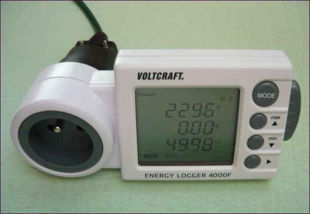
The comparative measurements below show, that even if the trafo in ALM 7006 has the highest power consumption and heating, it is still acceptable.
ALM 7004, ALM 7006, ALM 7010 transformer measurements of active power(W), apparent power(VA), power factor(cosΦ) and temperature.
There are 3 different dimensioned transformers used in these 3 ALMxxx devices. It was interesting for me to compare them.
The measurements were executed at 238 V on the primary winding.
Not loading - only the indicator and number LEDs are powered with current from secondary winding.
Loading was done with 3.6 V NiMH battery and the loading current was 160 mA.
Temperature was measured at the end of loading.
| ELV ALM | trafo properties | prim.win. resist.(Ω) | load max. (V / A) |
not loading (W / VA /cosΦ) | loading (W / VA /cosΦ) | temp. (°C) |
|---|---|---|---|---|---|---|
| ALM7004 | ? | 72 | 18 / 1 | 6.0 / 13.3 / 0.45 | 10.0 / 16.0 / 0.60 | 40 |
| ALM7006 | 2*8V / 300mA + 9.7V / 7A | 32 | 18 / 2 | 8.6 / 16.6 / 0.50 | 11.4 / 19.0 / 0.59 | 50 |
| ALM7010 | 2*8V / 500mA + 27V / 3.5A | 18 | 30 / 3.5 | 8.4 / 28.0 / 0.30 | 8.9 / 27.0 / 0.32 | 35 |


ELV ALM 7004 - same as ALM 7006 with maximal charging current only 1A.
Bought from second hand, discharging was not working.
The reason was a defective operating amplifier IC10D from quadruple OA TLC274.
I disconected the output and replaced it with one half of double OA LF412, which was disposable
and soldered it directly on the input pins of TLC274, as seen on the picture.


ELV ALM 7004 - another one.
I received it from Nicolas Z. The C22 was exploded, measuring C of it was therefore not relevant. But it was not short cutted. I have replaced it with another one with ESR < 1 Ω. The missing power cord was replaced by another one. Two green LEDs were also replaced, while they didn't work. Load, unload with test option were without any problems. On the pictures there is an arrow pointing to the place of the wrong capacitor. After all I have calibrated it.
Calibration: (Using a power supply giving 1-17V and min. 1A and an exact multimeter)
1. pressing ↑ and Start by power on, on the display comes U 1
2. after sourcing 1 Volt on output and pressing Eingabe, seeing on the display U17
3. after sourcing 17 Volt on output and pressing Eingabe, seeing on the display IO, after pressing Eingabe comes on the display 800, it means 800mA
4. connecting the ampermeter between the output holes it shows a value. This value ist to set on the display with ↑ and ↓
5. Ater pressing Eingabe some seconds with CAL on the display comes 800 on the display again.
6. Now connecting a power source with voltage between 5V and 10V, which can give minimal 1A with ampermeter connected serial.
7. The value read on the ampermeter is to be set on the display again with ↑ and ↓ and after pressing Eingabe is the calibration completed.


ELV ALM 7010 - NiCd, NiMH, Pb, Li-ion loading (charging) and measuring device with 2 outputs.
Socket for external temperature sensor, RS232 connectivity for PC controlling and data logging software.
Maximal charging voltage 28V, loading current maximal 3.5A settable. These 2 outputs work one after other,
not simultaneously.
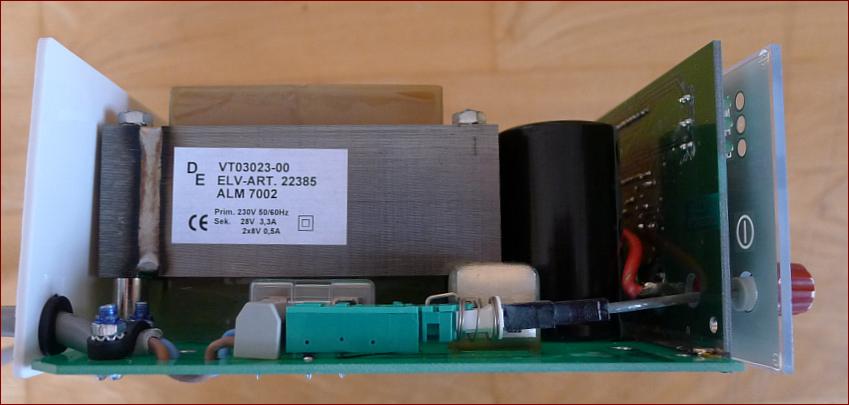
inside - trafo,
inside - detail,
inside - PCB.


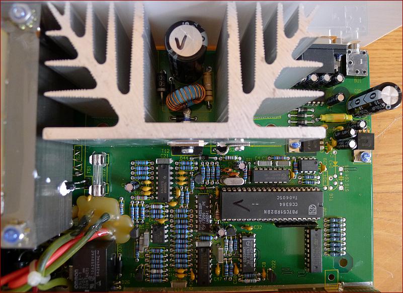
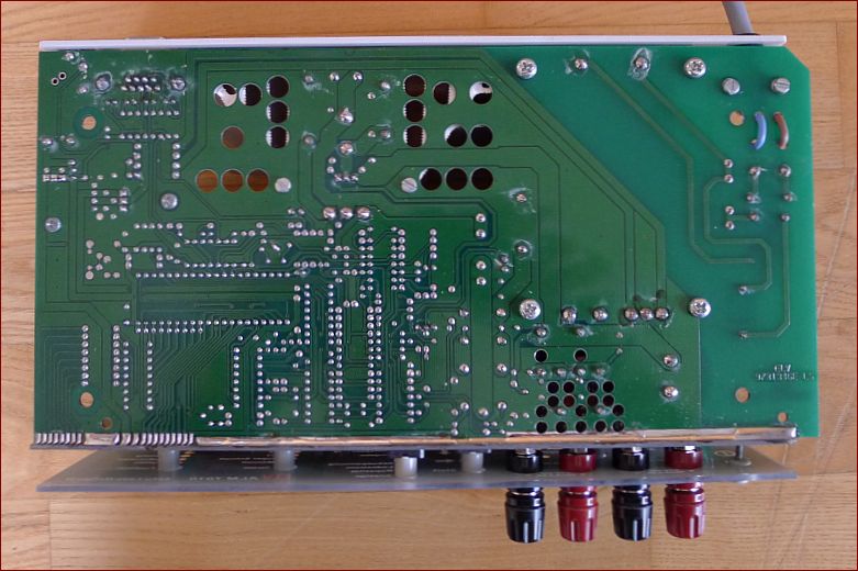
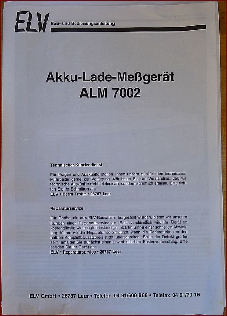
ELV ALM 7002 - NiCd, NiMH, Pb, Li-ion loading (charging) and measuring device with 2 outputs
as DIY kit. Socket for external temperature sensor.
Maximal charging voltage 28V, loading current maximal 3.5A settable,
bottom side of the main PCB,
documentation.

Trafo brum in ALM7010
I bought the ALM 7002 kit, because the ALM 7010 was giving a brumming (growling ?) sound of the net frequency.
As I know, that the trafos are same in ALM 7010 and ALM 7002 and an ALM 7002 kit was offered on ebay, I bought it.
After exchanging the trafo in ALM 7010 with trafo from the ALM7002 kit the situation was the same. I have then tried
to damp somehow the main PCB from the bottom box-part with success, but after mounting the upper box-part
the brumming sound came again.
I remembered, that in the valve radios the bigger trafos where tightened to the chassis with rubber washers placed between
the trafo and the chassis. I din't use rubber, because I hadn't any, but my next step was to take away the distance tubes (see picture)
and the tightening screws and to retract only the trafo plates with 4 shorter screws.
This brought success.
The distance of the trafo bottom part from PCB is now 1-2mm and the vibrations of the trafo body
are not taken over by the medium of the distance tubes to the PCB and from the PCB to the resonating box.
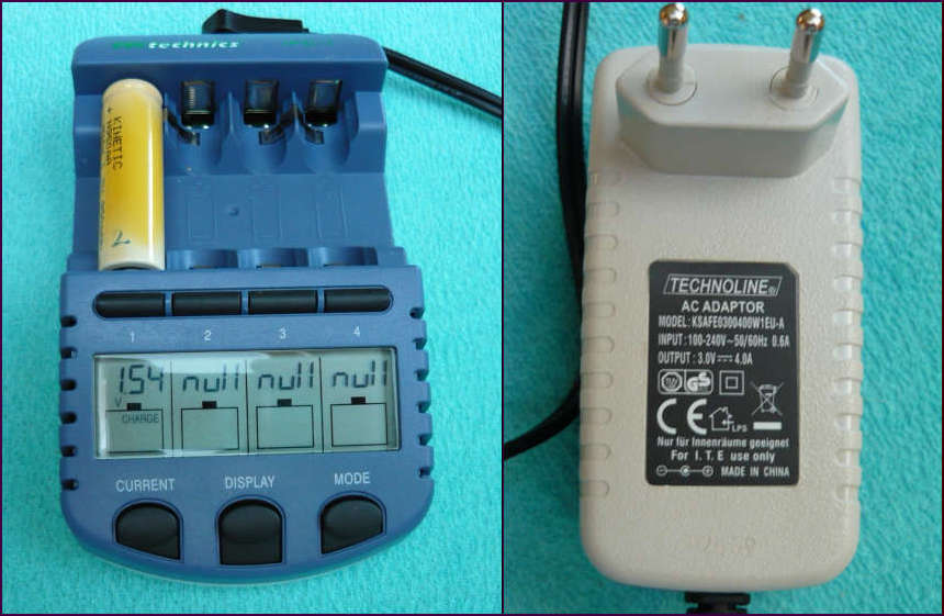
FK Technics IPC-1
AA, AAA NiCd, NiMH loader. 4 fully independent boxes, automatic-processor driven delta peak detection.
More or less same as Voltcraft IPC-1 or Technoline BC 1000.
Current (selection): 200, 500, 700, 1000, 1500 or 1800 mA.
Display: Voltage, current, time, capacity.
Modes (programs): charge, discharge, test(unload current=load current/2), refresh.
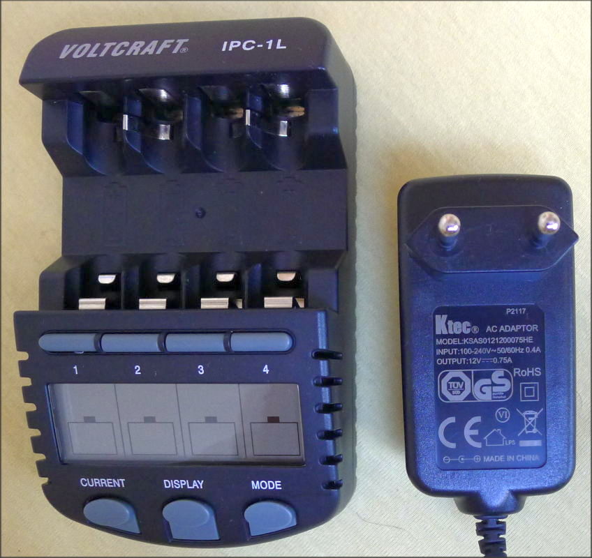
Voltcraft IPC-1L
AA, AAA NiCd, NiMH loader. 4 fully independent boxes, automatic-processor driven delta peak detection.
Current (selection): 200, 500, 700 mA.
Display: Voltage, current, time, capacity.
Modes (programs): charge, discharge, test(unload current=load current/2), refresh.
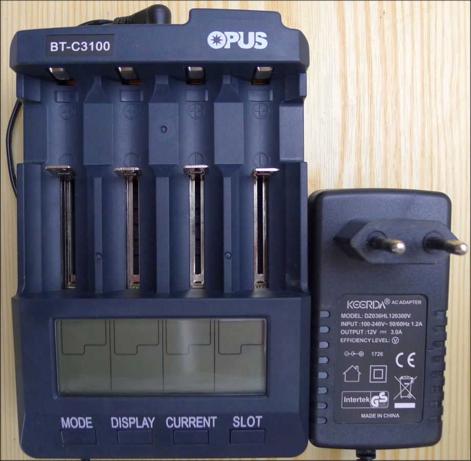
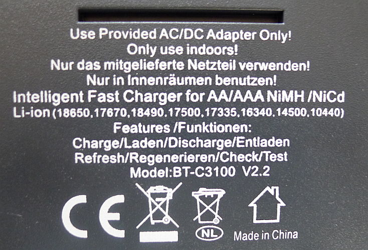
Opus BT-C3100
AA, AAA, and other suitable NiCd, NiMH, Li-ion loader.
4 fully independent boxes, automatic-processor driven delta peak detection,
quick-test for internal resistance.
Current for charging (selection): 200, 300, 500, 700, 1000, (if used only slots 1 and 4 also 1500, 2000) mA.
Current for discharge 200, 300, 500, 700, (1000 mA only for Li-ion).
Display: Voltage, current, time, capacity, internal reistance in mΩ.
Modes (programs): charge, discharge, refresh, test(unload current=load current), quick test.
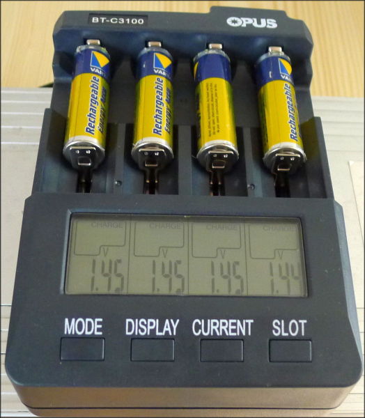
Slot: for chosen slot will be current and mode applied.
Quick-test (Ri in mΩ) for loaded accu (may be used also for alkaline batteries).
If Ri > 250 mΩ, then the load current may be lower as the chosen current.
Contact failure may cause additionally 30 mΩ and even more. Better contact pressure brings better value.
For instance a new full loaded 18650 Li-ion showed with Quick Test 120 mΩ, whereas with ELV RIM1000 measured 80 mΩ.
An internal fan works, if temperature is over 40°C. Over 60°C the loader stops loading.
If temperature falls under 40°C, loading continues.

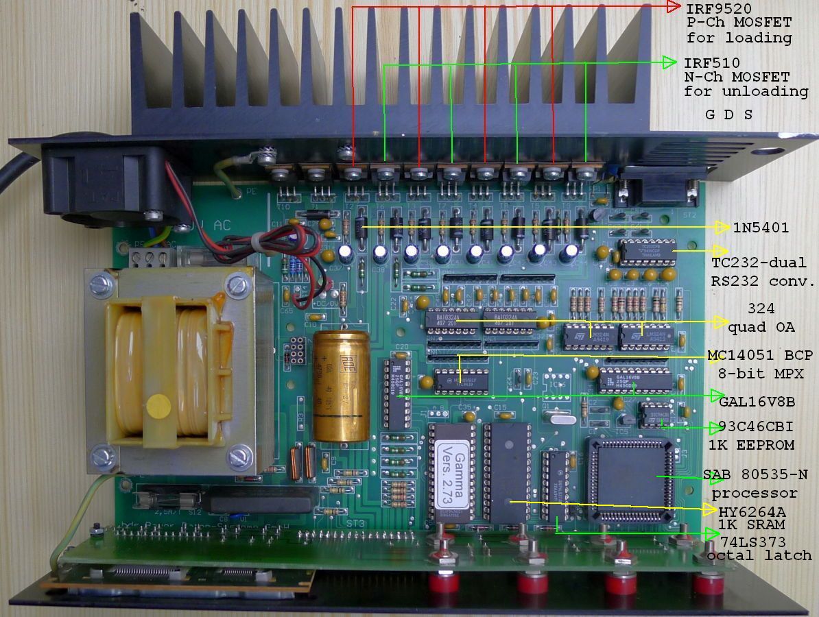
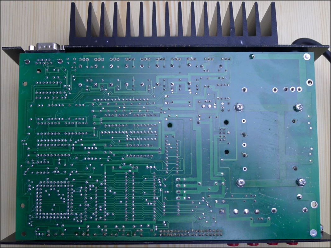
U.I. Modelltechnik Profiline Gamma
NiCd, NiMH, Pb loader. 4 independent boxes, processor SAB 80535-N driven.
Modes(programs): NiCd,NiMH: 1-12 cells charge, discharge, d-ch, ch-d-ch, refresh. Pb: 2V, 6V, 12V charge.
Current charge / discharge settable max. 1.7A all boxes together or max. 1A for one box.
Display: Voltage, current, by pushing CLEAR also time and capacity.
Charging with 10s current and 2s pause, voltage is measured continuously.
The difference between pause and load voltage depends on internal resistance Ri of the accumulator.
Discharging works without pause, voltage is measured under load.
The front panel is connected to the board by a connector. RS232 connector behind enables graphing on PC.
Current and charge voltage on the display is OK. But the discharge voltage is 0.2 V less as measured by a voltmeter.
For such case calibration of charge and discharge current and voltage is possible pushing both CLEAR and ENTER.
Here is the description of this device in german.
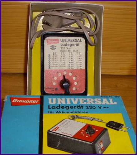
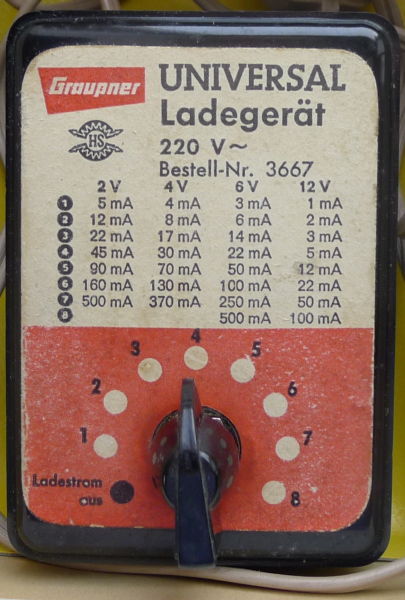
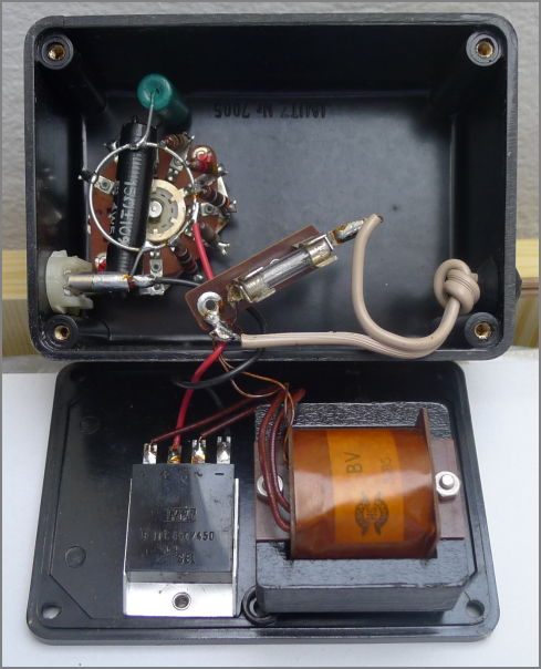
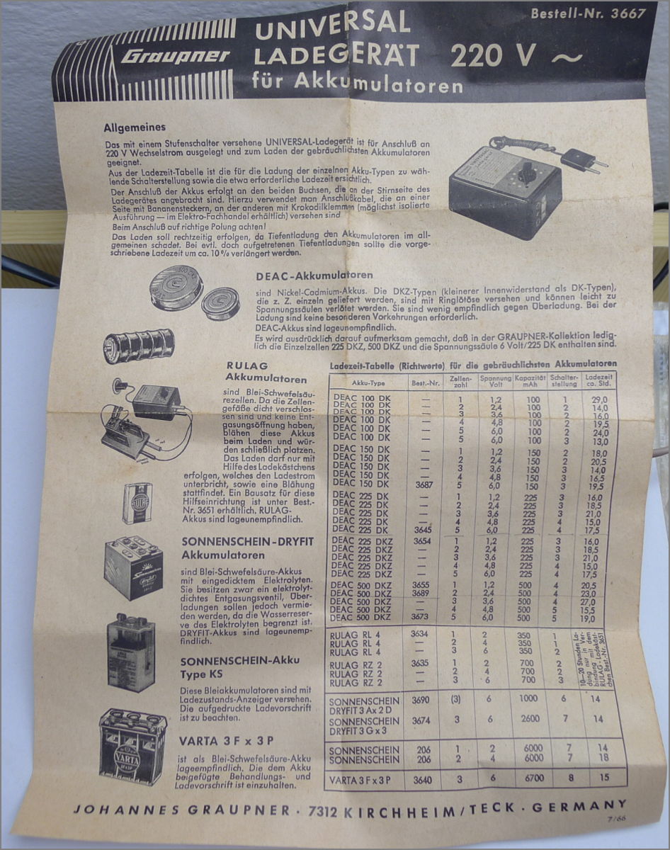
Accu loader Graupner for loading NiCd accus 0-12V with constant current.

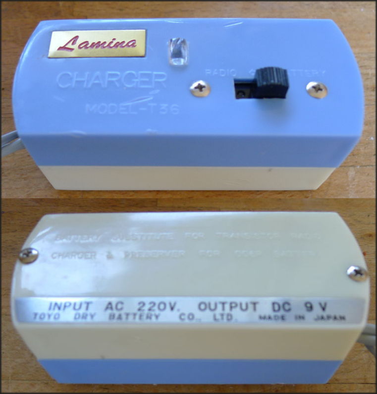
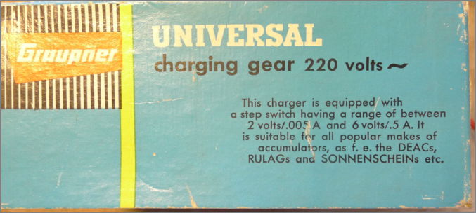
9V "E" battery charger or 9V external source Toyo Dry Battery Co., Ltd.: Lamina model T36.
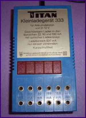
(2x)Accu loader Titan 333 for loading NiCd accus 0-12V with constant current 22-50-100-500 mA.
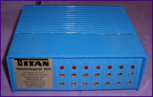
Accu loader Titan 603 for loading NiCd accus 0-12V with constant current 22-50-70-140-500 mA
Li-ion, Li-Po
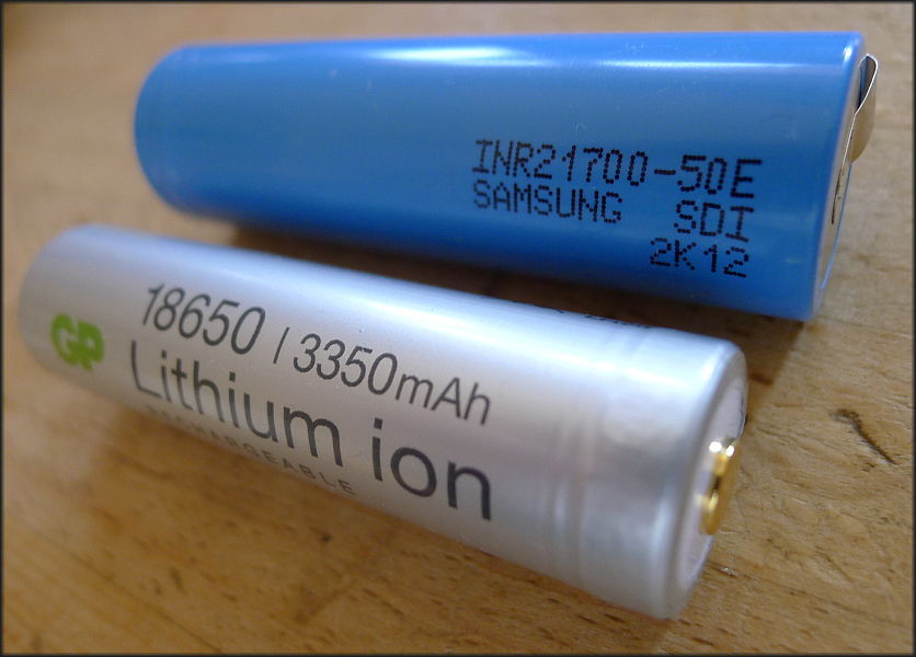
At the picture:
18650 (18x65 mm) with built-in protection. 3350 mAh Imax 5A. Measured Ri ~80 mΩ.
21700 (21x70 mm) with U-solder tags without protection 5000 mAh Imax 15A. Measured Ri ~25 mΩ.
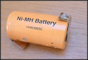
For comparison: 3000 mAh NiMH subC element measured Ri ~5 mΩ.
Ri measured with RIM1000 - see below and current pulses of 2A.
| Type (source Wikipedia) | diameter[mm] | length[mm] |
|---|---|---|
| AA | 14.5 | 50.5 |
| AAA | 10.5 | 44.5 |
| subC | 22.2 | 42.9 |
| C | 26.2 | 50 |
| D | 34.2 | 61.5 |
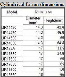
Li-ion types (sizes):
07540, 08570, 10180, 10280, 10440, 14250, 14430, 14500, 14650, 15270, 16340, 17500, 17650, 17670,
18350, 18490, 18500, 18650, 20700, 21700, 25500, 26500, 26650, 32600, 32650, 38120, 38140, 40152.
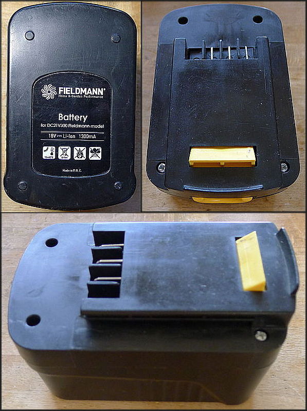
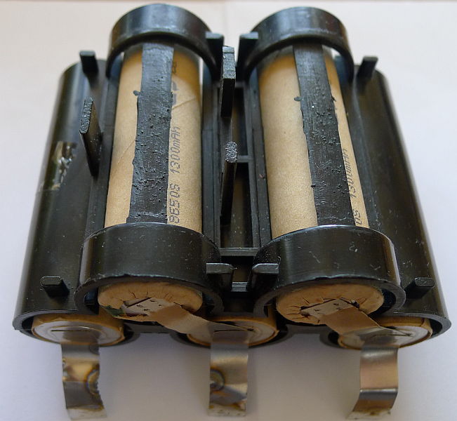
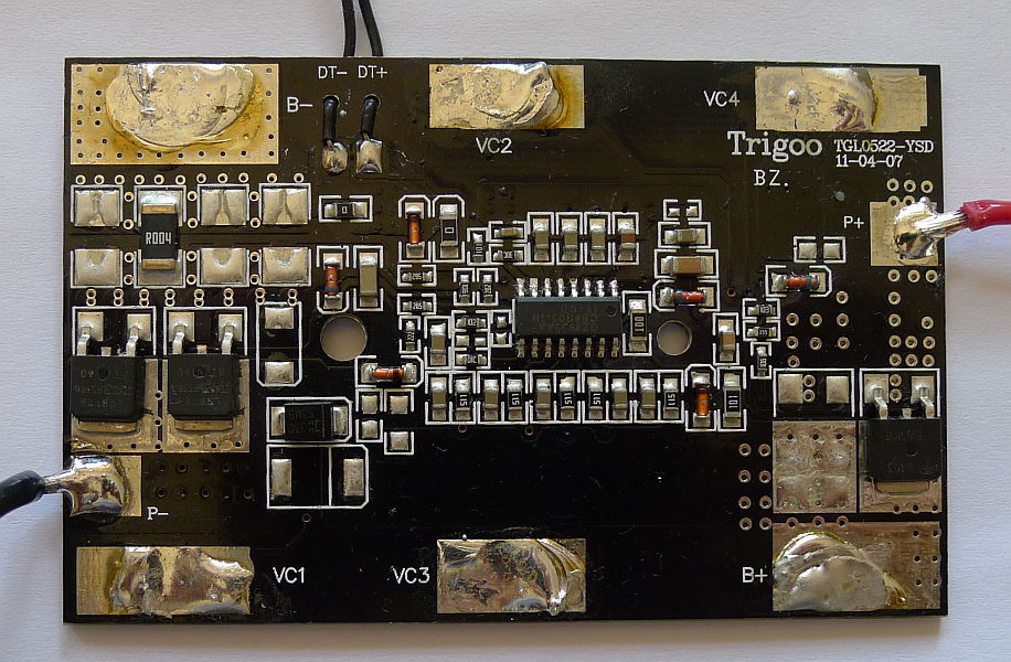

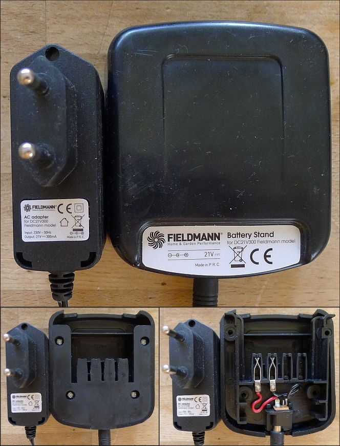
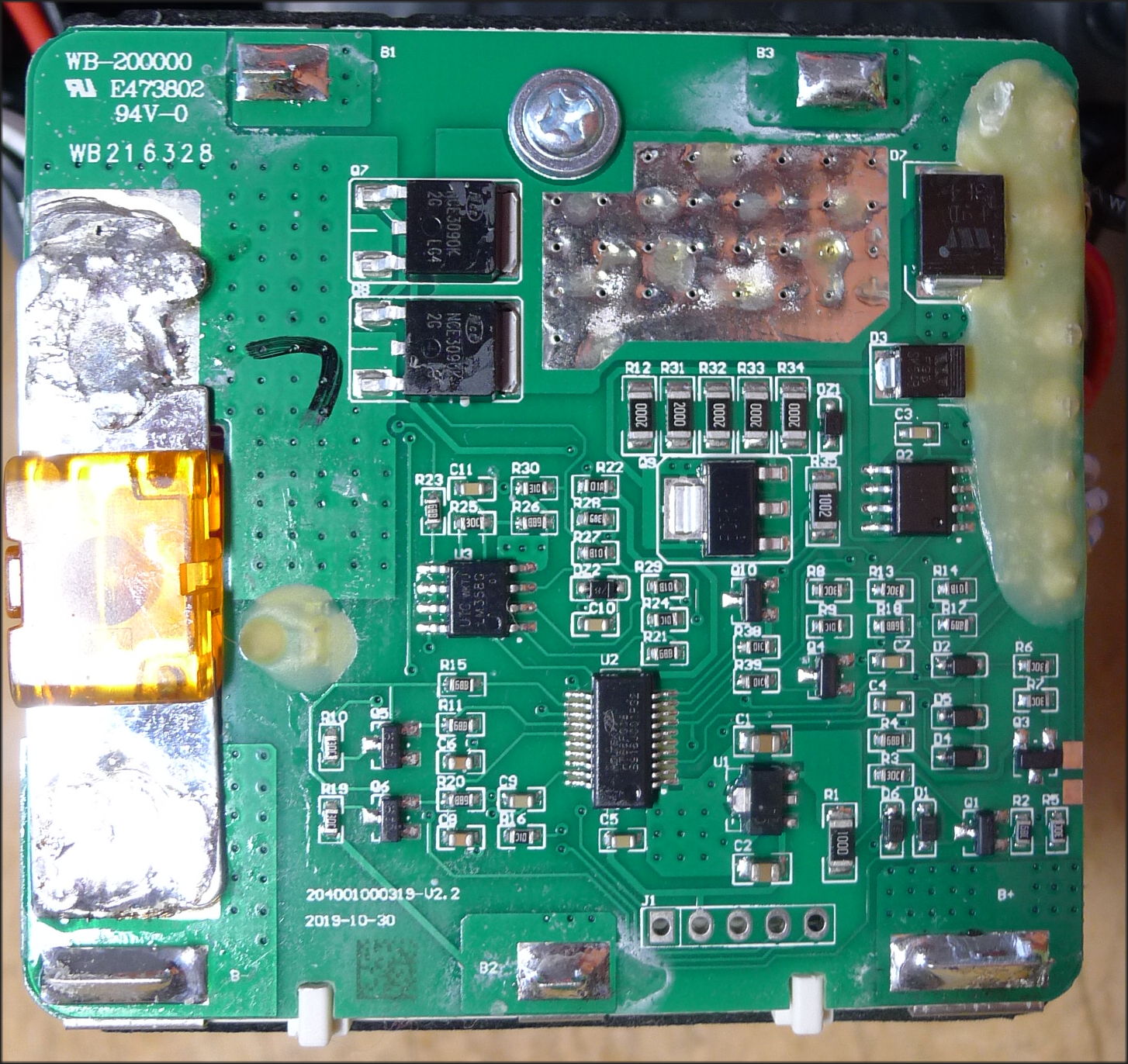
1300 mAh 18V Li-ion battery
for garden and other tools.
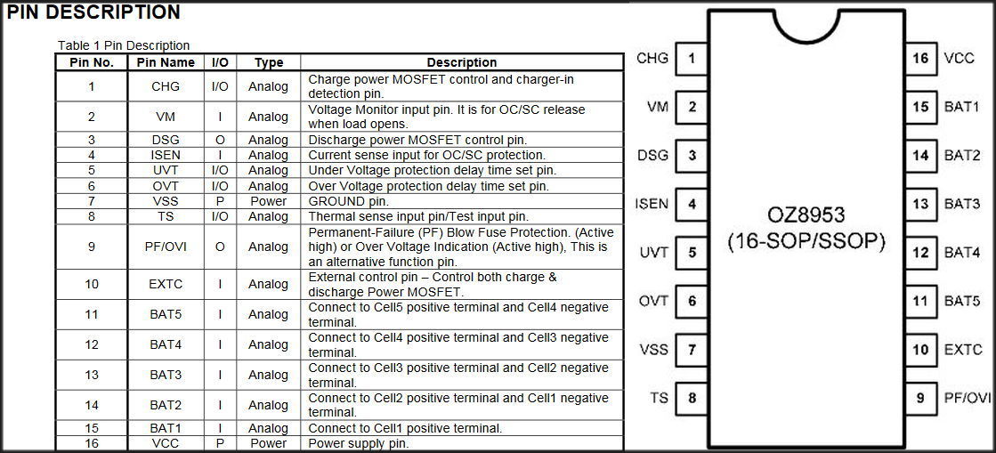
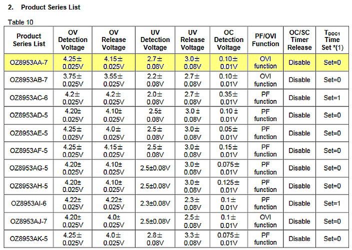
Control IC: OZ8953 AA7.
AA7 specific values
Load power device: 21V, 300mA =.
Measuring of 1 battery cell of type 18650 showed big waste of capacity (200 mAh), while Ri was still about 70 mΩ.
Another battery cell had only 60 mAh. The best two of these elements had still capacity 1160 mAh respectively 1040 mAh.
Capacity measured with ELV ALM 7010.
Ri measured with ELV RIM1000.
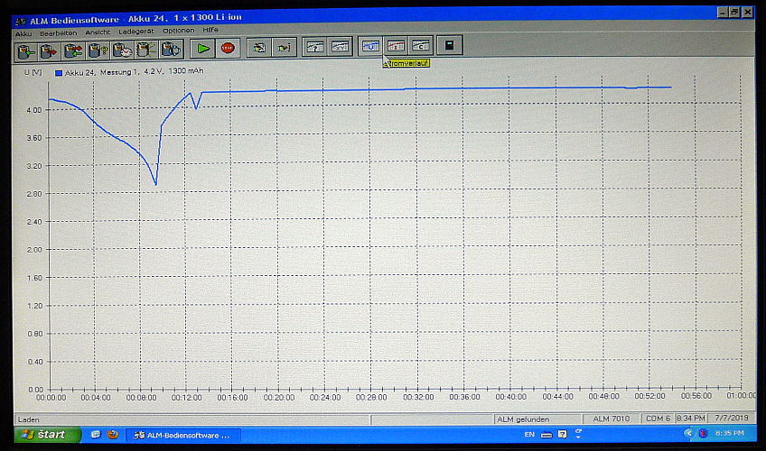
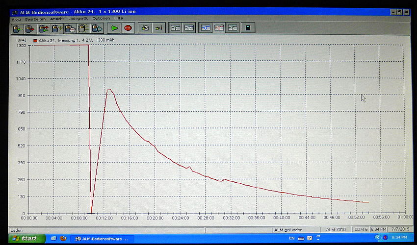
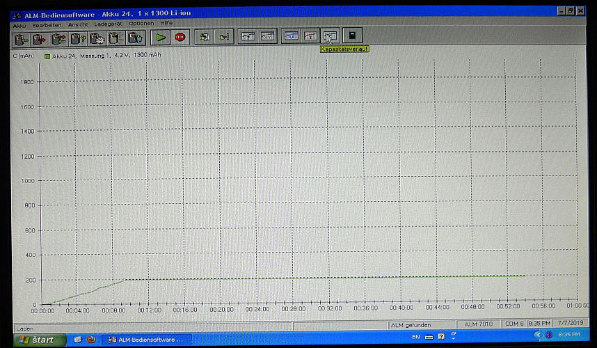
U, I, C graphs:
Using unload-load cycle of ELV ALM7010 by C/1 current 1300mA for 1300 mAh battery cell at reduced 200 mAh cell capacity.
Unloading of this used battery cell with current C/1 1300 mA lasted only ca 9 minutes because of reduced capacity of this cell.
Loading should work firstly with given constant current 1300mA, which even wasn't achieved, because of arriving limited voltage.
Achieving cca 4.22 V works loading at this constant voltage, where current goes gradually down and by cca 80 mA loading finishes.
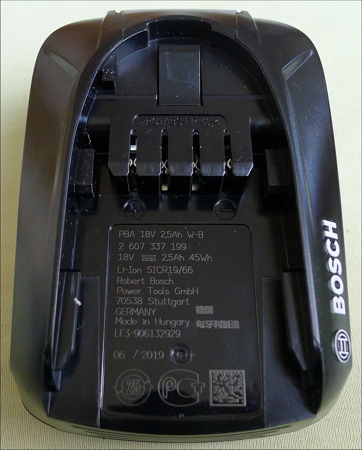

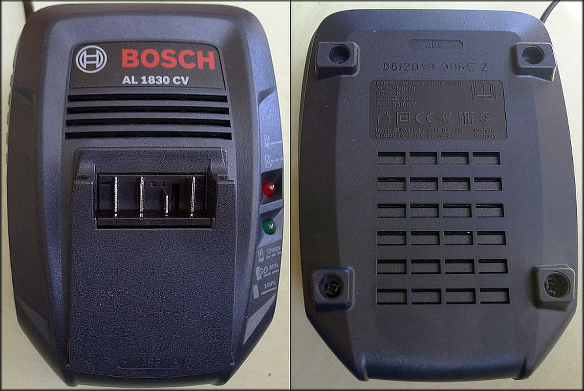

2,5Ah 18V Bosch Li-ion battery,
loader Bosch AL 1830 CV
for garden and other tools.
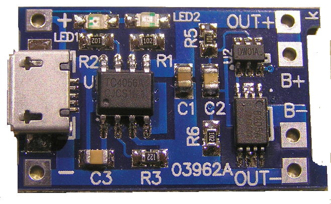
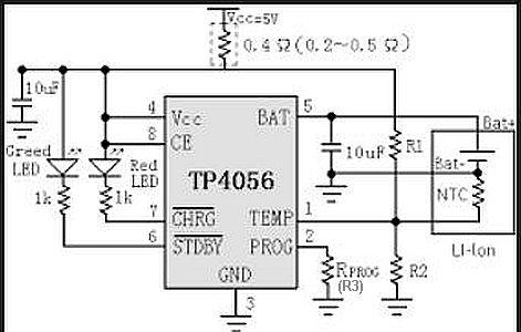
LiPo loader with TP4056 for 1 LiPo element. (Typically 18650)
With battery element protection. It exists a similar little device without battery protection - only for loading purposes withut OUT contacts to device taking current from the battery.
The loading current comes from a 4,5-6 V power supply through the micro USB or the contacts on both sides of it.
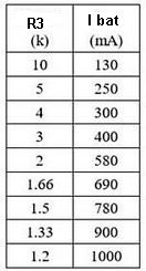
The maximal loading current is set by the Rprog or R3 wih 1.2 kΩ on 1 A at the constant current phase. It is possible to change it changing this resistor value. The maximum voltage 4,2 V is controled by TP4506. If the battery voltage is under cca 2,9 V, the charging works with a current cca 100 mA only. The full current comes, if the element exceeds 2,9 V.
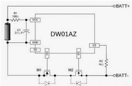
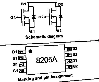
The battery protection contains aditionally IC DW01A and 8205, which unplug the battery element from the battery using device if voltage of the element falls under 2,4 V.
Usage of 4x 18650 accu pack in a garden trimmer grass-cutter: Accus are built inside and loaded with an adapter.
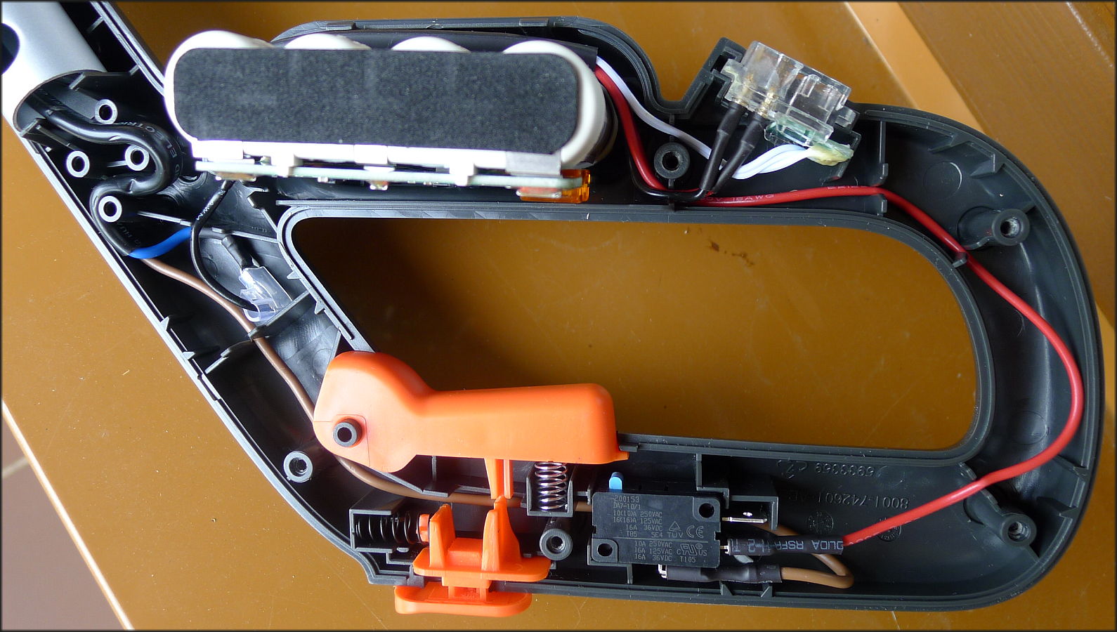
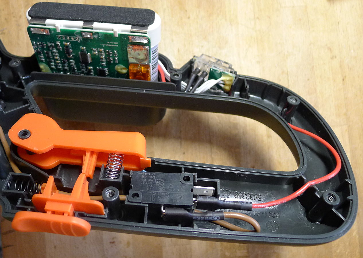

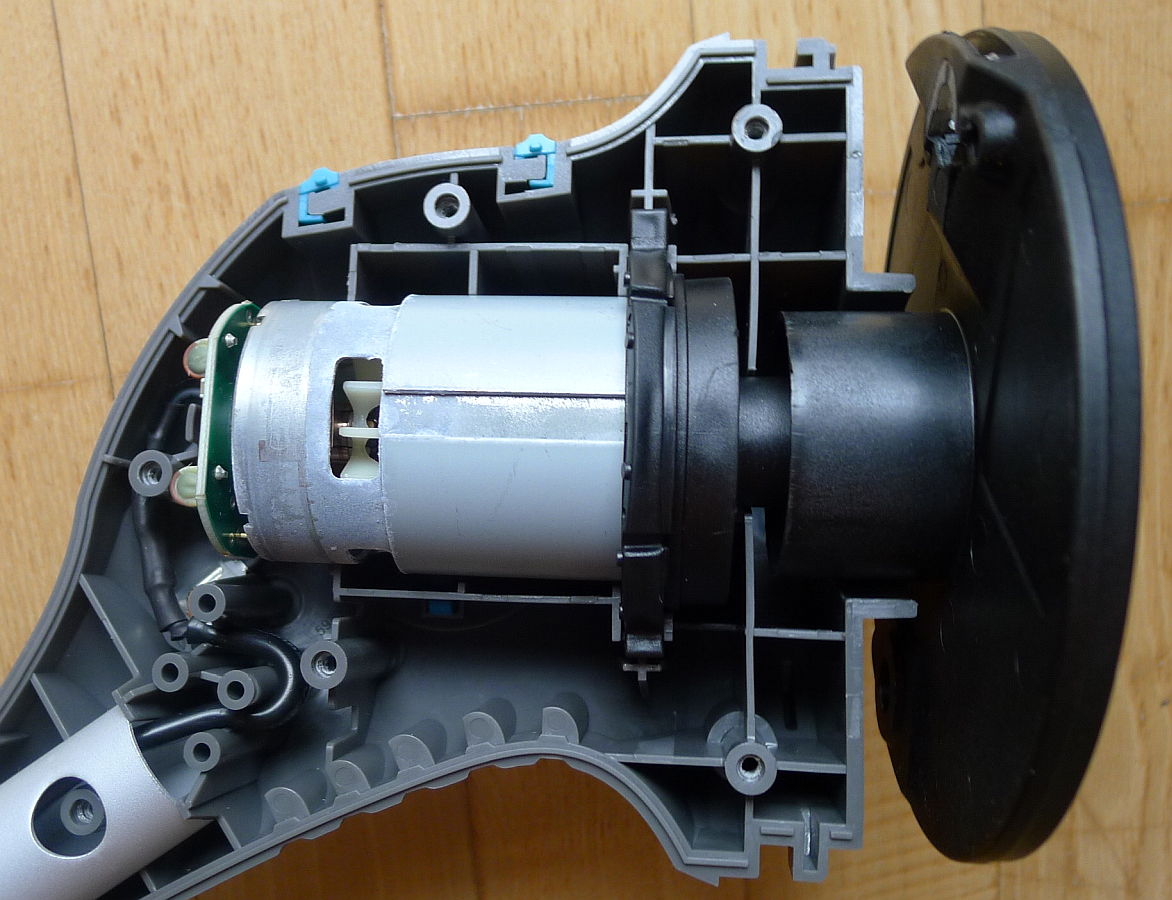
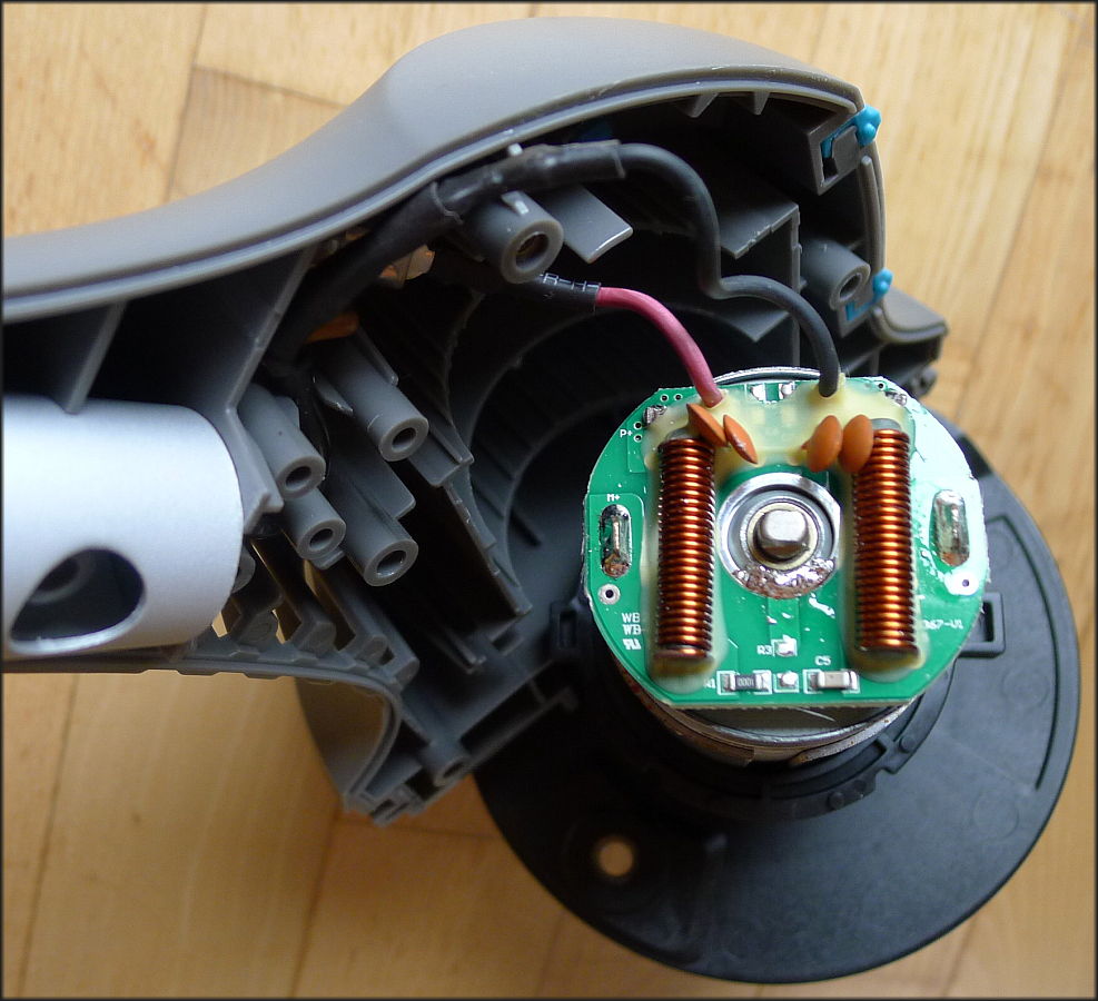
Motor with 14.4 V at free run without load only with the knife holder takes about 5 A, with 2.0 V 0.6 A.
The rounded knife holder is possible to unscrew as a female screw. The motor axle is ended by a male screw.
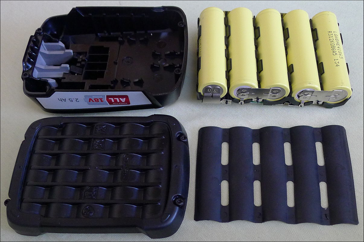
Usage of 5x 18650 accu pack in another garden trimmer grass-cutter:.
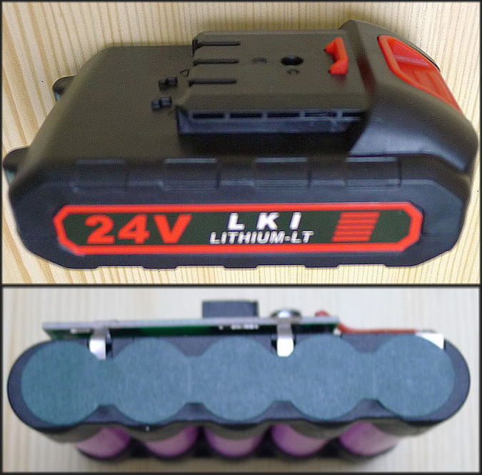

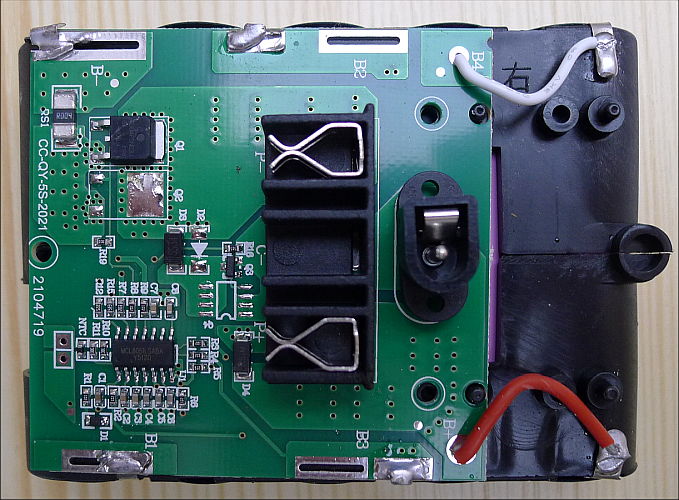
Five 18650 serial coupled elements give 3.6 x 5 = 18V. Full loaded I measured 20.5V. Not 24 V as written.
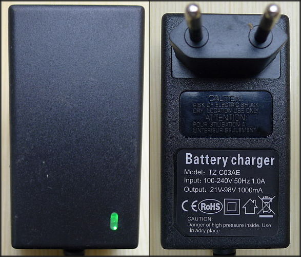
The net adapter for charging gives at 230VAC 22VDC and the light becomes red, if load resistor is less or equal 100 Ω.
Without load or with a load more as 100 Ω it is green and it signalises finishment of battery charging.
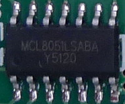
At the last picture we see, that the IC on the circuit board is MCL8051LSABA.
Measuring of accus and batteries
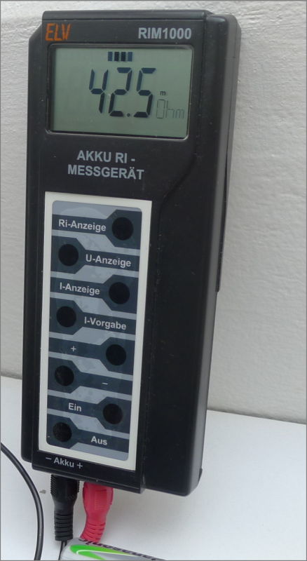
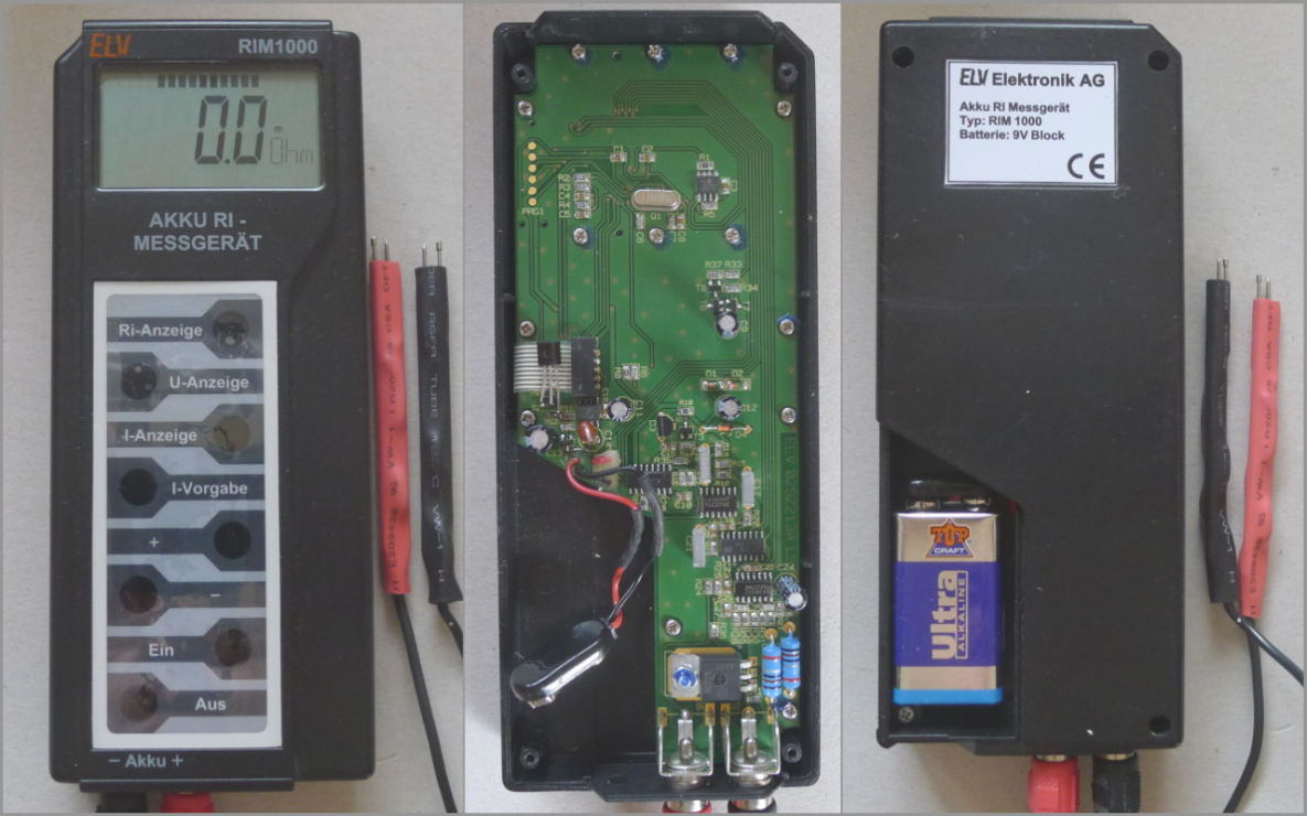
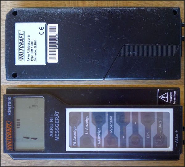
ELV RIM1000 or Voltcraft RIM1000
Internal resistance - Ri measurement device for accumulators, also for non rechargeables.
It was sold also as a kit, therefore a very good documentation exists in the web.
It works with short (5μs impuls) load 0.5A - 10A settable. My device has ca 1 µA consumpotion in off state.
Therefore it is better to take the battery off, when for a longer time not used.
I have replaced the SMD npn T2 transistor with a conventional one, because the T2 couldn't close even if its EB junction was short-connected. But it wasn't the T2, it was a short connection in the plastic foil connector between the keys and the board. Some chemical process has built a bridge between two silver lines of the plastic foil connector.
In another RIM1000 I had to replace the BUZ21L MOSFET. It has typical G trashold voltage 1.6V ± 0.4V, while BUZ21 typically 3V ± 1V.

| voltage & current source | usage | open volt.[V] | load curr.[A] | under load [V] | Ri [mΩ] |
|---|---|---|---|---|---|
| a c c u m u l a t o r s : | |||||
| AA Sanyo Eneloop 2400 mAh | new | 1.341 | 1 | 1.311 | 30 |
| AA 2000 mAh noname | 8 years | 1.320 | 1 | 400 | |
| AAA Sanyo Eneloop 800 mAh after charging | 2 years | 1.460 | 1 | 80 | |
| sub-C 3000 mAh accupack (12 elements) | 1 year heavy duty | 15.56 | 1 | 15.43 | 130 |
| the same accuppack | 15.56 | 5 | 14.91 | 130 | |
| for 1 sub-C element | 11 | ||||
| accupack NiCd 1300 mAh (6 elements) | 9 years | 7.62 | 1 | 130 | |
| b a t t e r i e s ( n o n r e c h a r g e a b l e s ) : | |||||
| AA lithium Energizer | 3 months | 1.756 | 1 | 1.631 | 125 |
| AA alkaline noname | 3 months | 1.533 | 1 | 1.353 | 180 |
| 9V alkaline battery Maxell (6 elements) | new | 9.6 | 1 | 7.8 | 1800 |
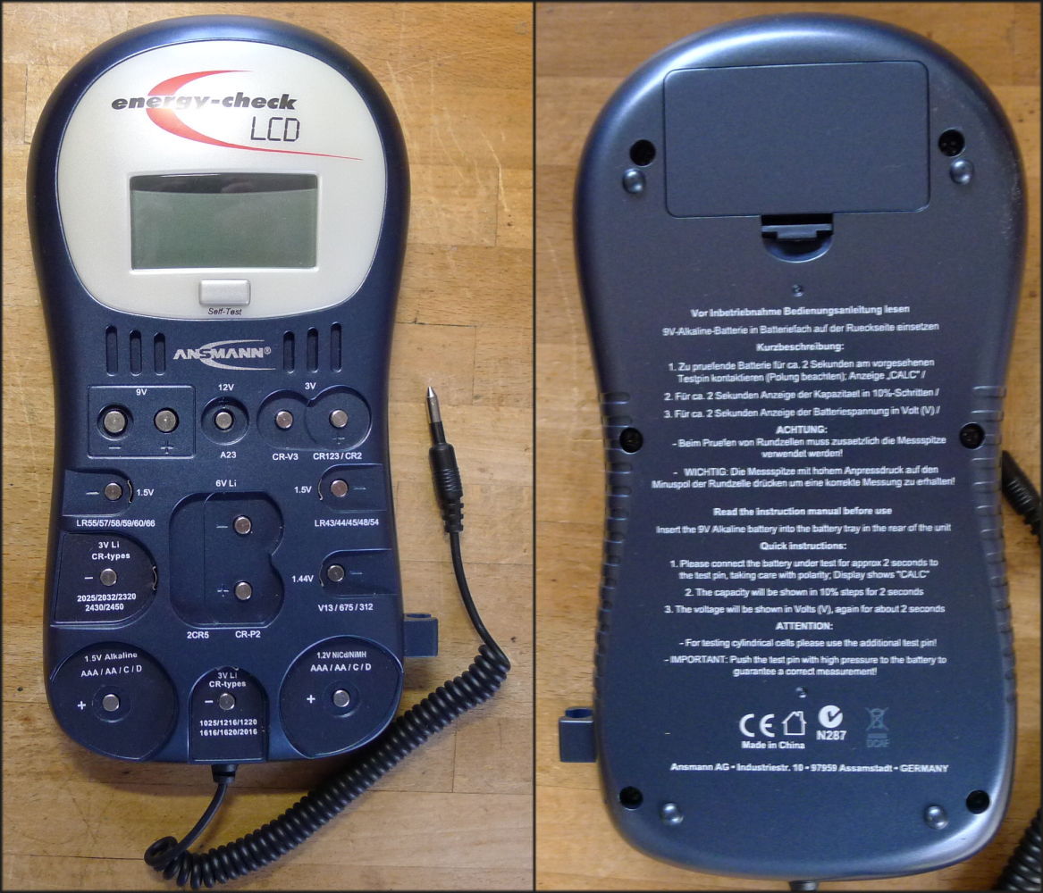
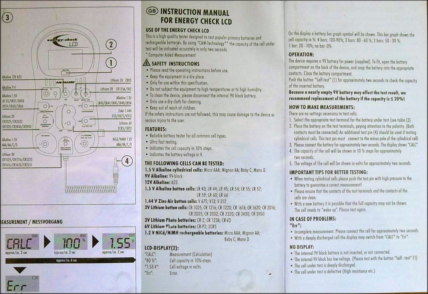
Ansmann Energy Check LCD
It is usable for battery and also for AA, AAA, C, D NiCd/NiMH accumulator.
The result is rest capacity in tenths of % and voltage under battery type specific load in duration of ca 2s.
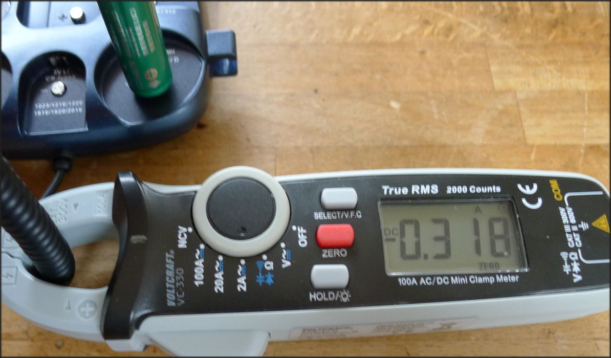
First I have measured the strength of electromagnetic field. the current values are not relevant
current values because there is no DC or AC current, there is a short, load dependant current pulse.
| type | displayed current value |
|---|---|
| AAA/AA/C/D accumulator | 300mA. |
| AAA/AA/C/D battery | 150 mA. | 9V battery | 40 mA | 12V A23 battery | 10 mA | 3V CR 2025, 2032, 2320, 2430, 2450 | 10 mA | 1.5V LR43, 44, 45, 48, 54 | 3 mA |
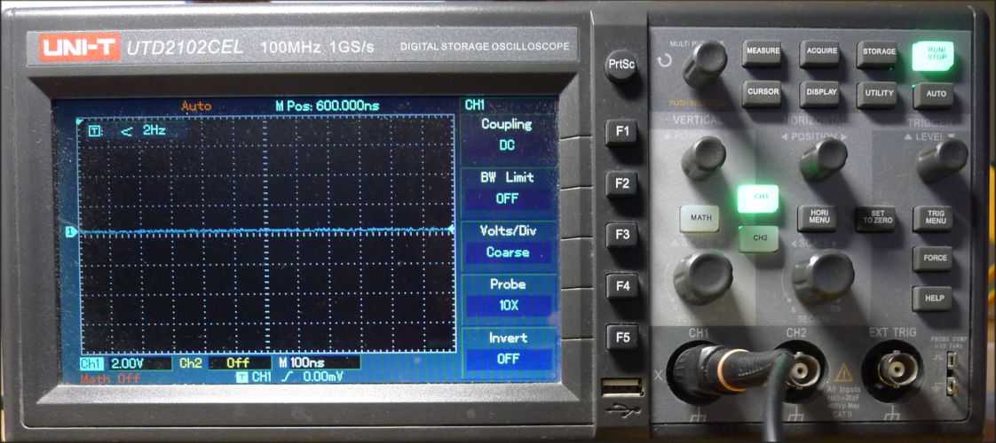
 After it I have used a 1 Ω resistance in series with the tested element and a 100 MHz scope
in DC mode, time basis 100 ns per segment, connected at the resistor ends.
It has shown a short 100 ns pulse.
On the 9V battery it was 2 V pulse and wirh the AA penlike element it was a 15 V pulse.
It means these short pulses where current pulses of 2 A and 15 A.
Therefore it is important to ensure a good contact between the battery and Ansmann device.
So it works like a inner resistance measurement device.
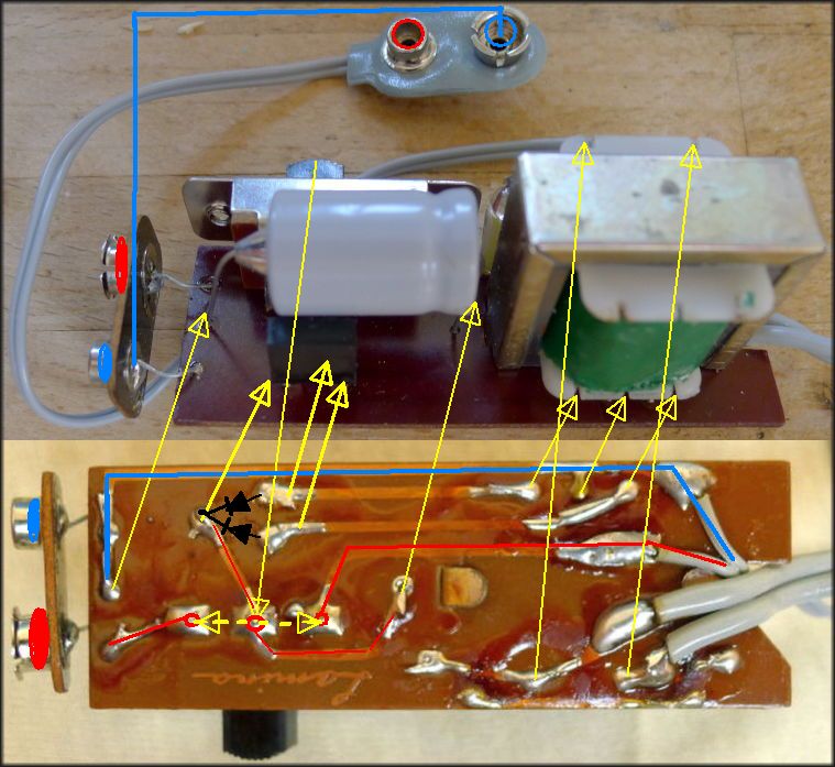
Wireless charging
In this case the secondary unit is a wireless doorbell, which has a 600 mAh Li-ion accumulator charged without using some connector facility,
only laying it onto the primary unit. To keep them correctly together help small mighty magnets in primary and secondary unit.
We can treat the primary unit as a transmitter and the secondary unit as a receiver. But they are inductive coupled, not using a resonance frequency for the energy transfer.
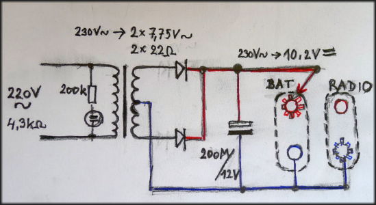
Primary unit:
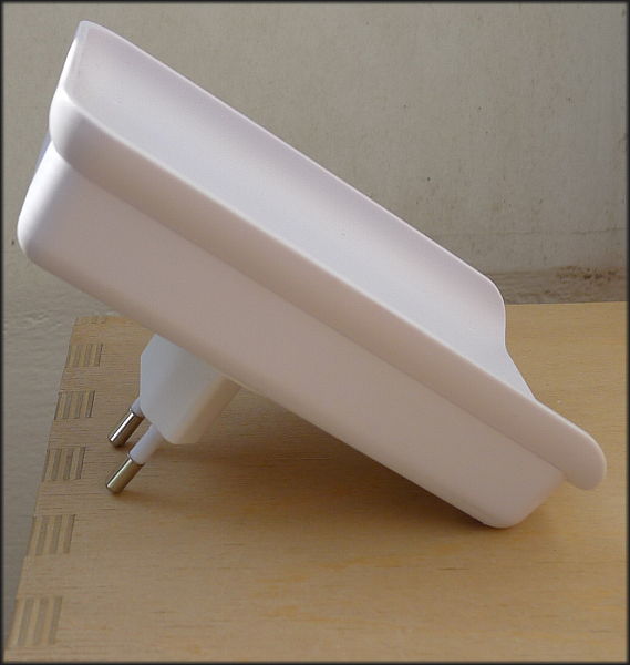

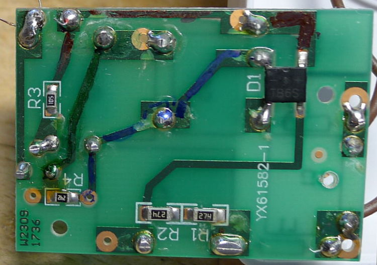
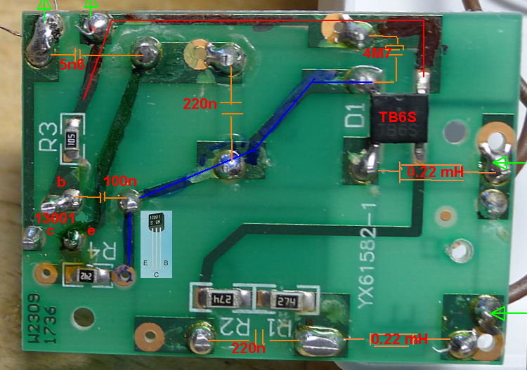
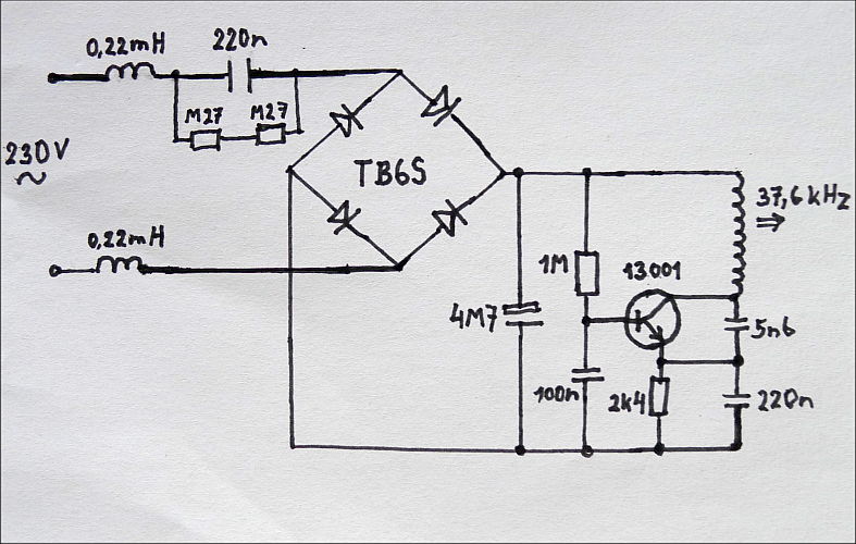
The frequency is about 36 kHz, peak voltage of the sinus wave measured on the coil is about 300 V.
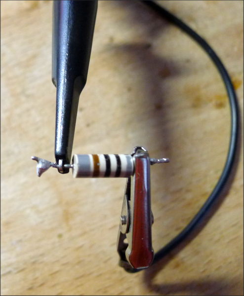
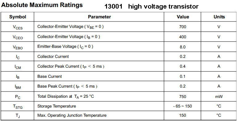
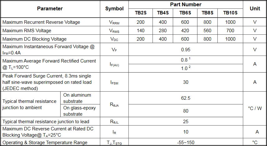
Parameters of transistor 13001 and
of bridge rectifier TB6S.
Inside of the secondary unit:
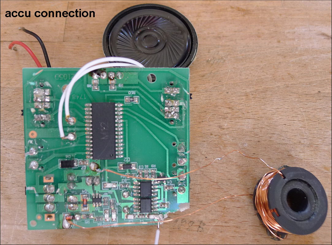
It loads a 600 mAh Li-ion with a current of 50 mA.
The secondary coil has about 60 turns (0.9Ω, 155 µH) and the peak voltage with open load is about 15 V.
With a 100 Ω load resistor falls the peak voltage down to 10 V.
With a 10 Ω load resistor falls the peak voltage down to 2 V.